


The following was published in CCJ's Air Brake Book, 11th edition, sponsored by SilverbackHD. CCJ's Air Brake Book is a complementary industry resource, courtesy of our partnership with SilverbackHD, the Technology and Maintenance Council and Commercial Vehicle Safety Alliance. You can download the entire Air Brake Book here.
Air brakes operate differently from hydraulic brake systems found on automobiles and light- duty trucks. All air brake systems differ somewhat depending on manufacturer design and application-specific options. This chapter will detail the three basic systems of air brakes you should be familiar with before attempting maintenance or replacement work.
Supply system
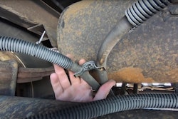
 The supply system provides pressurized air that actuates its components, and in many ways is the heart of the air brake system.SilverbackHD
The vehicle’s driver can monitor the air system pressure via a dash-mounted pressure gauge. If pressure in the system falls below 60 psi, a switch in the system must come on and send an electronic signal to a dash light or buzzer in the cab and alert the driver of a problem.
Air in the system is stored in air reservoirs (usually three or more per tractor) until it is needed. Check valves keep pressurized air from passing back through the compressor while it’s not running to make sure the air gets to where it is needed. Should the system become over-pressurized with too much air, “pop-off,” or safety, valves open to allow air to escape before damaging air lines, the reservoirs or other system components.
The air reservoir nearest the compressor is often called the supply tank (sometimes called a “wet” tank), because that is where atmospheric moisture condenses in the greatest quantities. Moisture is the biggest enemy of any air brake system, and great care must be taken to ensure a vehicle has the cleanest and driest air possible circulating through its brake system. To that end, reservoirs are equipped with either automatic or manually actuated drain valves allowing water to be purged from the system.


Air dryers then condense and remove any water not drained from the system by forcing air through a canister containing desiccant material. Prior to air dryers, alcohol sometimes was injected into the air system in cold weather to prevent any water from freezing and clogging air lines, but this practice is strongly discouraged. Alcohol will eat away at rubber components like seals.
Control system
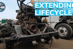
 Acquisition costs are higher for air disc brakes, but lifecycle cost and resale values can make up for that in the long run.SilverbackHD
The dual-control foot value is the main actuator in the system. It is actually two valves that operate simultaneously in response to input from the driver’s foot on the brake pedal. Two valves are needed because after leaving the supply tank, air in the system splits into two separate and protected brake circuits that are divided between the primary and secondary reservoirs. This backup source of air allows the driver to bring the vehicle to a complete stop in the event of a system failure.
When the driver steps on the brake pedal, air flows from the primary reservoir and through the primary portion of the dual-control foot valve to actuate the rear axle brakes. At the same time, air flows from the secondary reservoir through the secondary portion of the dual-control foot valve to actuate the front axle brakes. A two-way check valve senses the air pressure in both the primary and secondary air systems and allows the system with the highest pressure to actuate the trailer brakes (if present). Primary air also can be manually supplied to the trailer by means of a hand valve, which is usually found near the vehicle’s steering wheel. In addition, the two-way check valve actuates the vehicle’s stop light switch, thereby ensuring the stop lamps are actuated in the event of a failed circuit.
But it takes time to get air through a brake system in order to stop or slow a vehicle. Relay valves are used on trailers and the rear axles of long-wheel-based tractors to ensure faster system reaction time. These relay valves are directly supplied with system pressure and use air from the dual-control foot valve as a signal to quickly direct airflow to the brakes they serve. If the vehicle is equipped with an anti-lock braking system (ABS), ABS valves are combined with relay valves on a trailer to supply modulated air to the anti-lock brake mechanism.
The delivery pressure of the relay valves is affected by their respective “crack” pressure setting. Crack pressure is the amount of air pressure required at the input from the foot valve before the relay valve will send air pressure to the brakes controlled by that valve. Crack pressure is an important element of brake timing and balance. It is determined for each axle on the vehicle by how heavily loaded the axle served by the valve is, how big the brakes are and how aggressive the linings are on those brakes.
A valve that cracks at too low a pressure for a given axle can cause that axle’s brakes to operate at a lower control pressure while the other axles do not and can lead to a significant braking imbalance. Likewise, a valve that cracks at too high a pressure can also cause braking imbalance for the same reasons. Because of incompatibility and wear issues, OEMs and component manufacturers through the Technology & Maintenance Council, the Society of Automotive Engineers and other industry organizations have worked hard to standardize valve crack characteristics. (For more information, refer to SAE recommended practice J1505 for brake balance procedures and J1860 for recommended component labeling practices.)
Once a stopped truck is ready to go, having air travel all the way back through the system would cause a noticeable lag between the time the driver removed his foot from the brake pedal to when the brakes released. To combat this problem, quick-release valves located near the brakes they serve quickly expel air from the system and allow quick brake release times.
Dash-mounted air valves inside the cab control air pressure to the parking brakes. In most cases, these are spring-applied brakes, which are actuated gradually by descending air pressure in the brake system. Conversely, when air is applied by pushing in on the dash control valve (parking control valve), the brakes will be fully released in the 60- to 70-psi range. This provides a fail-safe feature in the event all air is lost; the vehicle still can be parked and can be used as part of an emergency brake system.
The tractor protection valve maintains air pressure in the lines that carry air to the trailer if one is being pulled behind the vehicle. “Gladhands” – quick-connect fittings at the rear of the tractor – supply air to the trailer. In the event of an emergency – either a substantial leak in the air lines or a trailer breakaway – the tractor protection valve automatically closes to maintain air pressure in the tractor circuit. The valve also works in conjunction with the dash-mounted trailer parking brake valve to shut off air to the trailer circuit before disconnecting the trailer from the tractor.
The trailer spring brake valve – sometimes called the multi-function valve – releases the trailer park brakes and controls the charging of the trailer service reservoirs. It also works with an integral check valve to isolate a failed reservoir, which otherwise would allow the parking brakes to apply automatically, whether they were needed or not.
Foundation and parking brake systems
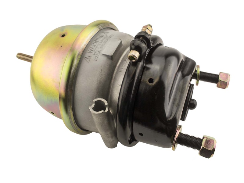
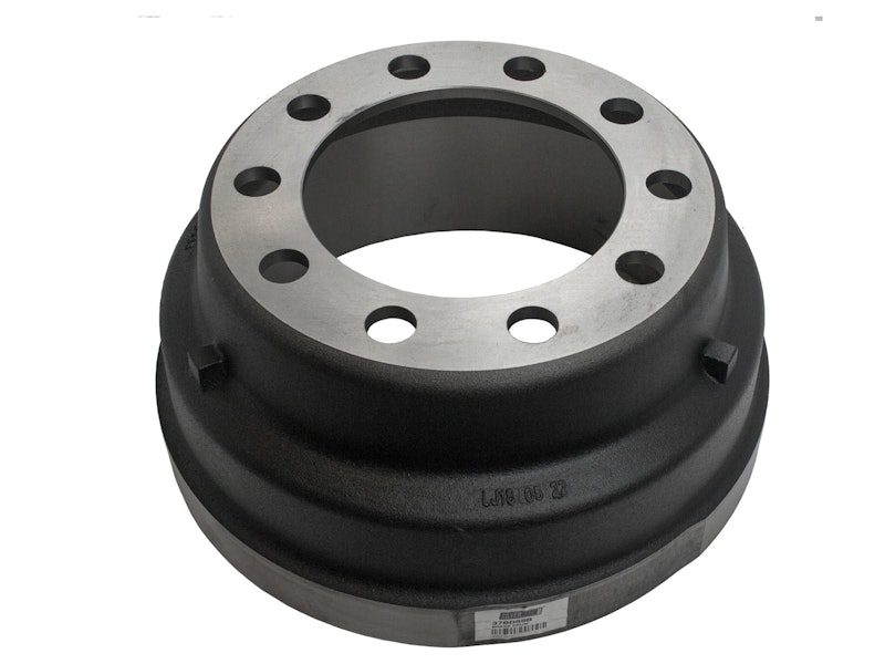 A drum brake wheel end would need to be replaced by an air disc brake with a brake chamber, hub and rotor axle.SilverbackHD
As the system exerts air pressure on the diaphragm, the pushrod on the other side of the diaphragm extends outward. The force this pushrod exerts as it moves outward is a result of the amount of air pressure applied in psi combined with the area of the diaphragm in square inches.
For example, if 100 psi of air pressure is supplied to a pressure chamber with a 16-square-inch diaphragm, then the amount of force generated at the pushrod would be 1,600 pounds. Using the same formula, a 100-psi application of air pressure into a chamber with a 30-square-inch diaphragm will produce 3,000 pounds of pushrod force. Obviously, it is important to make sure brake chambers are matched properly to avoid severe brake imbalance problems.
In an S-cam brake system, the pushrod is connected to a lever called a brake adjuster (also called a slack adjuster). When actuated by air pressure in the brake chamber, the pushrod forces the brake adjuster outward. The brake adjuster is connected to a shaft that runs perpendicular to the plane formed by it and the pushrod. As the pushrod extends outward, it causes the brake adjuster to rotate the shaft. As the shaft rotates, it turns an S-shaped cam located between the brake shoes. This action forces the brake shoes apart, placing them against the inner portion of the brake drum, creating the friction needed to slow the vehicle. The amount of friction produced depends on several factors, most notably the size of the brake shoes, the coefficient of friction (aggressiveness) of the brake lining material and the mass and heat rejection of the drum.
Brake shoes – their lining material, in particular – are self-destructive by nature. In other words, the friction created by pushing the shoe against the brake drum creates heat and naturally wears away the brake lining as it works to slow the vehicle. The brake adjuster is equipped with a slack adjustment mechanism to compensate for constantly wearing brake linings and ensure consistent stopping force when the brakes are applied. This system, as its name implies, automatically adjusts as the brake lining wears away so that the pushrod does not have to travel farther and farther to apply braking pressure. Without the brake adjuster, the pushrod soon would be unable to extend far enough outward to apply the brakes.
Brake adjusters have another important function as well. They are force multipliers – essentially levers that multiply brake forces in proportion to their length. A 5 1/2-inch-long brake adjuster, for example, converts 1,000 pounds of force at the pushrod into 5,500 inch- pounds of torque at the brake camshaft. Because of this, the brake adjuster’s length and the brake chamber size are the two components most commonly altered to meet different vehicle braking requirements. Automatic Brake Adjustors (ABA) are rated by an “AL factor” — the product of chamber area (type) times the length of the ABA.
Engineers express the product of these two values as the brake system’s “AL factor.” This factor, when multiplied by 60-psi air pressure, is the industry standard for braking calculations. Using this formula, 60 psi of air pressure applied to an air chamber with a 16-square-inch diaphragm (the “A” portion of the AL factor) creates 960 pounds of pushrod force. This becomes 3,840 pound-feet of torque applied to the brake camshaft when multiplied by a 4-inch brake adjuster.
Brake chambers do more than simply apply the service brakes in everyday driving. On rear tractor axles and trailer axles, they also apply the parking brakes. These spring brakes use a second chamber with a second diaphragm and a powerful spring. A driver must push in the dash-mounted parking brake valves in order to put a vehicle in normal service. Once these valves are in the “run” (pushed-in) position, air pressure is applied to the spring chamber on the side of the diaphragm opposite the spring itself. Air pressure on the diaphragm compresses the spring, holding the parking brakes off as long as there is adequate air pressure in the system. This does not affect the action of the service brakes in normal vehicle operation.
When the vehicle is parked, the driver pulls the dash valves out. This action exhausts the air holding back the spring brakes, allowing them to deploy and hold the vehicle in place. FMVSS 121 typically defines vehicle parking minimum requirements for loaded vehicles.
As a safety precaution, the spring brakes are designed to apply automatically in the event of a loss of air pressure in the brake system. If air pressure is lost for any reason, the parking spring brake overcomes hold-off air pressure in the secondary brake chamber, and the brakes are applied automatically to provide emergency stopping power.